The capacitor screen can realize multi-touch control by increasing the electrodes of mutual capacitance. In short, the screen is divided into blocks. A group of mutual capacitance modules are set in each area to work independently, so the capacitor screen can independently detect the touch control of each area, and after processing, the multi-touch control can be realized simply.
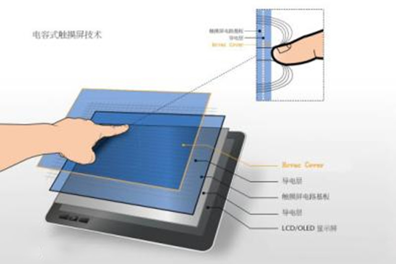
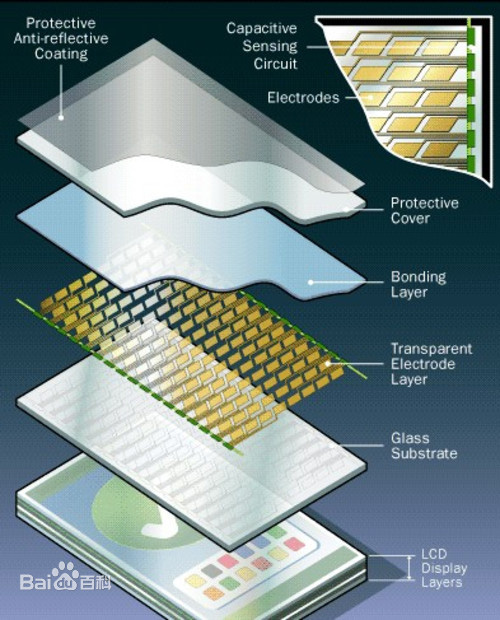
Capacity Touch Panel CTP (Capacity Touch Panel) works by current sensing of the human body. The capacitor screen is a four-layer composite glass screen. The inner surface of the glass screen and the interlayer are each coated with one layer of ITO (nano indium tin metal oxide), and the outermost layer is silica glass protective layer only 0.0015mm thick. The interlayer ITO coating is used as the working surface, and four electrodes are drawn from four corners.
Projective capacitor panel
The projective capacitive touch screen etches different ITO conducting circuit modules onto two ITO conducting glass coatings. The figures etched on the two modules are perpendicular to each other, and you can think of them as sliders that change continuously in the X and Y directions. Because the X and Y structures are on different surfaces, a capacitor node is formed at their intersection. One slider can be used as the drive line and the other as the detection line. When current is passed through one wire on the drive line, if a signal of capacitance change comes from the outside, it will cause a change in the capacitor node on the other wire. Capacitance changes can be detected through the connected electronic loop measurement, and then through A/D controller converted into a digital signal to the computer for calculation processing to obtain (X, Y) axis position, so as to achieve the purpose of positioning.
During operation, the controller supplies power to the drive line in turn, forming a specific electric field between each node and the conductor. Then, by scanning the sensing lines one by one, capacitance changes between electrodes are measured to realize multi-point positioning. When the finger or touch medium approaches, the controller quickly detects the capacitance change between the touch node and the wire, and then confirms the touch position. One shaft is driven by an array of AC signals, and the response on the touch screen is measured via electrodes on the other shaft. Users refer to this as "traversal" induction or projection induction. The sensor is plated with an X - and Y-axis ITO pattern. When the finger touches the surface of the touch screen, the capacitance value below the contact increases as the distance between the contact points increases. A continuous scan on the sensor detects changes in capacitance values, and the control chip calculates the contact points and returns them to the processor.

Post time: Apr-25-2023


