There are many kinds of interfaces for touch screen display, and the classification is very fine. It mainly depends on the driving mode and control mode of TFT LCD Screens. At present, there are generally several connection modes for color LCDs on mobile phones: MCU interface (also written as MPU interface), RGB interface, SPI interface VSYNC interface, MIPI interface, MDDI interface , DSI interface, etc. Among them, only the TFT module has RGB interface.
MCU interface and RGB interface are more widely used.
MCU interface
Because it is mainly used in the field of single-chip microcomputers, it is named. Later, it is widely used in low-end mobile phones, and its main feature is that it is cheap. The standard term for the MCU-LCD interface is the 8080 bus standard proposed by Intel, so I80 is used to refer to the MCU-LCD screen in many documents.
8080 is a kind of parallel interface, also known as DBI (Data Bus interface) data bus interface, microprocessor MPU interface, MCU interface, and CPU interface, which are actually the same thing.
The 8080 interface is designed by Intel and is a parallel, asynchronous, half-duplex communication protocol. It is used for external expansion of RAM and ROM, and later applied to the LCD interface.
There are 8 bits, 9 bits, 16 bits, 18 bits, and 24 bits for data bit transmission. That is, the bit width of the data bus.
Commonly used are 8-bit, 16-bit, and 24-bit.
The advantage is: the control is simple and convenient, without clock and synchronization signal.
The disadvantage is: GRAM is consumed, so it is difficult to achieve a large screen (above 3.8).
For LCM with MCU interface, its internal chip is called LCD driver. The main function is to convert the data/command sent by the host computer into RGB data of each pixel and display it on the screen. This process does not require dot, line, or frame clocks.
LCM: (LCD Module) is the LCD display module and liquid crystal module, which refers to the assembly of liquid crystal display devices, connectors, peripheral circuits such as control and drive, PCB circuit boards, backlights, structural parts, etc.
GRAM: graphics RAM, that is, the image register, stores the image information to be displayed in the chip ILI9325 that drives the TFT-LCD display.
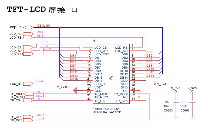
In addition to the data line (here is 16-bit data as an example), the others are chip select, read, write, and data/command four pins.
In fact, in addition to these pins, there is actually a reset pin RST, which is usually reset with a fixed number 010.
The interface example diagram is as follows:

The above signals may not all be used in specific circuit applications. For example, in some circuit applications, in order to save IO ports, it is also possible to directly connect the chip select and reset signals to a fixed level, and not to process the RDX read signal.
It is worth noting from the above point: not only Data data, but also Command are transmitted to the LCD screen. At first glance, it seems that it only needs to transmit pixel color data to the screen, and unskilled novices often ignore the command transmission requirements.
Because the so-called communication with the LCD screen is actually communicating with the LCD screen driver control chip, and digital chips often have various configuration registers (unless the chip with very simple functions such as 74 series, 555, etc.), there is also a direction chip. Need to send configuration commands.
Another thing to note is: LCD driver chips using 8080 parallel interface need built-in GRAM (Graphics RAM), which can store data of at least one screen. This is the reason why screen modules using this interface are generally more expensive than those using RGB interfaces, and RAM still costs.
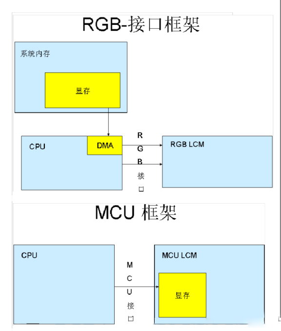
In general: the 8080 interface transmits control commands and data through the parallel bus, and refreshes the screen by updating the data to the GRAM that comes with the LCM liquid crystal module.
TFT LCD Screens RGB interface
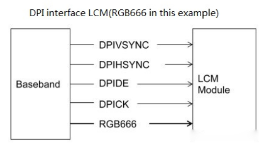
TFT LCD Screens RGB interface, also known as DPI (Display Pixel Interface) interface, is also a parallel interface, which uses ordinary synchronization, clock, and signal lines to transmit data, and needs to be used with SPI or IIC serial bus to transmit control commands.
To some extent, the biggest difference between it and the 8080 interface is that the data line and control line of the TFT LCD Screens RGB interface are separated, while the 8080 interface is multiplexed.
Another difference is that since the interactive display RGB interface continuously transmits the pixel data of the entire screen, it can refresh the display data itself, so GRAM is no longer needed, which greatly reduces the cost of LCM. For interactive display LCD modules with the same size and resolution, the touch screen display RGB interface of the general manufacturer is much cheaper than the 8080 interface.
The reason why the touch screen display RGB mode does not need the support of GRAM is because the RGB-LCD video memory is acted by the system memory, so its size is only limited by the size of the system memory, so that the RGB-LCD can be made in a larger size, Like now 4.3" can only be considered entry-level, while 7" and 10" screens in MIDs are beginning to be widely used.
However, at the beginning of the design of MCU-LCD, it is only necessary to consider that the memory of the single-chip microcomputer is small, so the memory is built into the LCD module. Then the software updates the video memory through special display commands, so the touch screen display MCU screen often cannot be made very large. At the same time, the display update speed is slower than that of RGB-LCD. There are also differences in display data transfer modes.
The touch screen display RGB screen only needs video memory to organize data. After starting the display, LCD-DMA will automatically send the data in the video memory to the LCM through the RGB interface. But the MCU screen needs to send the drawing command to modify the RAM inside the MCU (that is, the RAM of the MCU screen cannot be written directly).

The display speed of touch screen display RGB is obviously faster than that of MCU, and in terms of playing video, MCU-LCD is also slower.
For the LCM of the touch screen display RGB interface, the output of the host is the RGB data of each pixel directly, without conversion (except for GAMMA correction, etc.). For this interface, an LCD controller is required in the host to generate RGB data and point, line, frame synchronization signals.
Most large screens use RGB mode, and the data bit transmission is also divided into 16 bits, 18 bits, and 24 bits.
Connections generally include: VSYNC, HSYNC, DOTCLK, CS, RESET, some also need RS, and the rest are data lines.


The interface technology of interactive display LCD is essentially a TTL signal from the perspective of level.
The hardware interface of the interactive display LCD controller is at TTL level, and the hardware interface of the interactive display LCD is also at TTL level. So the two of them could have been directly connected, mobile phones, tablets, and development boards are directly connected in this way (usually connected with flexible cables).
The defect of TTL level is that it cannot be transmitted too far. If the LCD screen is too far away from the motherboard controller (1 meter or more), it cannot be directly connected to TTL, and conversion is required.
There are two main types of interfaces for color TFT LCD screens:
1. TTL interface (RGB color interface)
2. LVDS interface (package RGB colors into differential signal transmission).
The liquid crystal screen TTL interface is mainly used for small-sized TFT screens below 12.1 inches, with many interface lines and short transmission distance;
The liquid crystal screen LVDS interface is mainly used for large-size TFT screens above 8 inches. The interface has a long transmission distance and a small number of lines.
The large screen adopts more LVDS modes, and the control pins are VSYNC, HSYNC, VDEN, VCLK. S3C2440 supports up to 24 data pins, and the data pins are VD[23-0].
The image data sent by the CPU or graphics card is a TTL signal (0-5V, 0-3.3V, 0-2.5V, or 0-1.8V), and the LCD itself receives a TTL signal, because the TTL signal is transmitted at a high speed and long distance The time performance is not good, and the anti-interference ability is relatively poor. Later, a variety of transmission modes were proposed, such as LVDS, TDMS, GVIF, P&D, DVI and DFP. In fact, they just encode the TTL signal sent by the CPU or the graphics card into various signals for transmission, and decode the received signal on the LCD side to obtain the TTL signal.
But no matter which transmission mode is adopted, the essential TTL signal is the same.
SPI interface
Since SPI is a serial transmission, the transmission bandwidth is limited, and it can only be used for small screens, generally for screens below 2 inches, when used as an LCD screen interface. And because of its few connections, the software control is more complicated. So use less.
MIPI interface
MIPI (Mobile Industry Processor Interface) is an alliance established by ARM, Nokia, ST, TI and other companies in 2003. complexity and increased design flexibility. There are different WorkGroups under the MIPI Alliance, which define a series of mobile phone internal interface standards, such as camera interface CSI, display interface DSI, radio frequency interface DigRF, microphone/speaker interface SLIMbus, etc. The advantage of a unified interface standard is that mobile phone manufacturers can flexibly choose different chips and modules from the market according to their needs, making it faster and more convenient to change designs and functions.
The full name of the MIPI interface used for the LCD screen should be the MIPI-DSI interface, and some documents simply call it the DSI (Display Serial Interface) interface.
DSI-compatible peripherals support two basic operating modes, one is the command mode, and the other is the Video mode.
It can be seen from this that the MIPI-DSI interface also has command and data communication capabilities at the same time, and does not need interfaces such as SPI to help transmit control commands.
MDDI interface
The interface MDDI (Mobile Display Digital Interface) proposed by Qualcomm in 2004 can improve the reliability of mobile phones and reduce power consumption by reducing connections. Relying on Qualcomm's market share in the field of mobile chips, it is actually a competitive relationship with the above MIPI interface.
The MDDI interface is based on LVDS differential transmission technology and supports a maximum transmission rate of 3.2Gbps. The signal lines can be reduced to 6, which is still very advantageous.
It can be seen that the MDDI interface still needs to use SPI or IIC to transmit control commands, and it only transmits data itself.
Post time: Sep-01-2023


